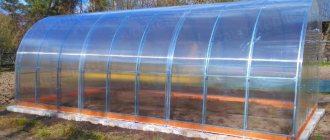
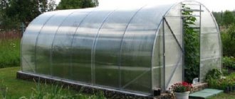
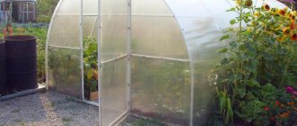
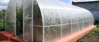
Greenhouses "Harvest": review of positive qualities
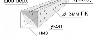
Greenhouses in this series can boast of durability, which is greatly facilitated by the V-shaped galvanized profile made of high-quality steel (some models use profiled pipes).
The technological effectiveness of the series is expressed in the original method of fastening the sheet covering, which does not require screws and bolts.
Universal sizes - thanks to the modular design, the greenhouse can be extended or shortened by lengths that are multiples of 2 meters.
Important advantages at the time of purchase are transportability and affordable cost.
At the buyer’s request, the manufacturer includes cellular polycarbonate in the greenhouse kit, which, in principle, is the norm; more details about choosing cellular polycarbonate can be found in the article. It is pleasantly surprising that this polycarbonate, which is used for the ends of the greenhouse, is already cut, which eliminates the need to do it yourself. It would seem like a trifle, but it reduces time and labor costs, especially if you do not have experience in cutting polycarbonate.
Greenhouses "Harvest" are presented in a series of several models; we will try to evaluate the merits of each model separately to make it easier to make a choice.
"Harvest Elite"
This model has an arched design, parameters - 400x300x210, material - profile steel pipes, galvanized on the outside and inside.
The following can be added to the standard kit at the buyer’s request:
- polycarbonate sheets in the required quantity;
- additional vents mounted in the roof of the greenhouse for better ventilation;
- additional arcs to increase the strength of the frame;
- LED bulbs;
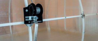
- automatic machine with greenhouse ventilation function.
The greenhouse is supplied disassembled; it must be assembled on site, which in principle should not cause difficulties, since all the necessary components and parts are included in the basic kit; in addition, the product is accompanied by instructions, and quite detailed video instructions are posted on the manufacturer’s website.
True, DachaDecor.ru considers knowledge of some nuances useful and therefore will give a couple of useful tips for assembling a greenhouse.
Before starting assembly, it is wise to prepare the necessary tools, you will need:
- a screwdriver of the appropriate size;
- screwdriver with reverse (if necessary, you can get by with a screwdriver)
- grinder for cutting polycarbonate (an alternative option is a mounting knife)
- drill with drill bits for self-tapping screws;
- pliers;
- M7 socket wrench.
It is more convenient to assemble the end elements of the greenhouse on a flat surface.
It is recommended to cover the assembly area with a sheet of plywood or fiberboard.
As a rule, there is always a gap between the base and the lower trim profile, which has to be masked with boards, but there is another option - to use a strip of linoleum from the remnants after repairs for this.
When sheathing doors and windows with polycarbonate, on the side in which they open, leave an extra 2-3 cm to cover the gap that appears between the frame and the moving element (door, window).
It is not recommended to increase the size of the functional holes present in the greenhouse frame, otherwise the manufacturer may refuse warranty service, and this may weaken the structure. The kit does not include washers that secure the external ties under the polycarbonate sheet, so if necessary, you will have to use your own.
Since 2013, a new model has been produced - “Elite Absolute”, which can withstand loads of up to 200 kg/m2 due to the smaller distance between the arcs, which is 60 cm.
Greenhouse "Urozhay-PK 4 m"
Greenhouse "Urozhay-PK 4 m"
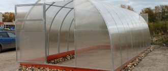
General view of the greenhouse (width 3 m, length 4 m, height 2.15 m)
ASSEMBLY INSTRUCTIONS Greenhouse “Urozhay-PK4 m”
Thank you for purchasing our product. The products we offer are distinguished by the high quality of component materials, and the modern manufacturing method guarantees resistance to mechanical stress throughout the entire service life, provided that the assembly and installation instructions, as well as the care of the product, are followed. We wish you good harvests and hope that our products will fully satisfy your expectations.
1.
BASIC TECHNICAL DATA
Greenhouse “ Urozhay-PK 4”
m" is intended to create a microclimate favorable for growing garden crops in summer cottages and household plots.
The frame of the greenhouse is made of galvanized V-shaped profile 0.8 mm thick and is assembled using screws (m4x10, m4x14) and nuts.
Covering: cellular polycarbonate and U-profile. Attention!
Not included in the package, must be purchased separately
.
To cover the greenhouse you need three sheets of cellular polycarbonate measuring 2.1 x 6 m and 29 pieces. endings (U-profile). Cellular polycarbonate is installed with a strictly defined side outward, which has a protective layer. The packaging film from the covering must be removed after cutting out the parts, before installing them on the frame. The covering at the ends of the greenhouse frame is secured with nuts (m4) and screws (m4x14, m4x25) with galvanized washers, and the top covering is fixed with clamping ties. Attention!
The mounting hardware is designed for a coating thickness of 4mm. Greenhouse " Urozhay-PK 4"
m" is equipped with two ends with opening doors with vents and one greenhouse frame reinforcement. The greenhouse delivery set consists of four packages.
Also, if desired, you can additionally install reinforcements for the greenhouse frame, an upper arched opening window, extend the length of the greenhouse frame to 6 m, 8 m, etc. a multiple of two, extensions 2 m long and install a partition - amplifier. Attention! Sold separately .
The frame of the greenhouse can be installed either on a wooden frame, the recommended board is 50x150 mm with dimensions of 3x4 m (not included in the delivery package, made independently )
, as well as by digging into the ground; for this purpose, the delivery set includes supports for fixing in the ground.
Greenhouse dimensions:
Length 4m
Width 3m
Height 2.15m (when installed in the ground)
2.35m (when installed on a wooden frame)
The weight of the greenhouse frame is no more than 60 kg
Attention! The manufacturer reserves the right to make changes to the design of the greenhouse without notifying the consumer.
2.
EQUIPMENT OF THE GREENHOUSE “
Harvest-PK4
”
| No. | the name of detail | Part length (mm) | Quantity (PC.) |
| 1 | Arc profile | 1610 | 21 |
| 2 | Arch extension | 860 | 14 |
| 3 | Arch extension support | 100 | 18 |
| 4 | Stringer | 1363 | 21 |
| 5v | Door post parts (upper) | 1145 | 4 |
| 5n | Door post parts (lower) | 1145 | 4 |
| 6 | Doorway lintel | 906 | 4 |
| 7 | Middle end cross member | 793 | 4 |
| 8 | Lower end cross member | 1004 | 4 |
| 9 | End jib | 1553 | 4 |
| 10v | Door pillar (upper) | 941 | 4 |
| 10n | Door pillar (lower) | 941 | 4 |
| 11 | Door cross member | 845 | 8 |
| 12 | Door jib | 993 | 4 |
| 13 | Window stand | 548 | 4 |
| 14 | Window cross member | 785 | 4 |
| 15 | Window jib | 894 | 2 |
| 16 | Corner | — | 18 |
| 17 | Bracket for fixing end cover | — | 10 |
| 18 | Arch reinforcement parts | 1468 | 3 |
| 19 | Arch reinforcement parts | 725 | 2 |
| 20 | Arch reinforcement parts | 400 | 2 |
| 21 | Hook for fixing doors and windows | 250 | 2 |
| 22 | Turntables for locking doors and windows | 100 | 4 |
| 23 | Tension tape | 5790 | 7 |
| 24 | Short tie tape | 350 | 7 |
| 25 | Door and window hinges | — | 8 |
| 26 | Screw M4 x 10 | — | 380 |
| 27 | Screw M4 x 14 | — | 160 |
| 28 | Screw M4 x 25 | — | 80 |
| 29 | Screw M4x35 | — | 7 |
| 30 | Nut M4 | — | 600 |
| 31 | Pressure washer | — | 120 |
Note: The cellular polycarbonate covering and
U -profile (the final strip of protection of the polycarbonate cellular from dirt and insects) are not included in the delivery package.
Screw configurations are subject to change. Markings on parts of positions No. 1, No. 2, No. 3, No. 4 may not be on all parts, but on one part. GENERAL ASSEMBLY INSTRUCTIONS
1. Frame parts are installed so that the side flanges of the profile face the covering.
2. The item number indicated in the package corresponds to the part number in the pictures and is indicated by the corresponding markings on the parts in the packaging. The marking of some parts has indexes: in
- top,
n
- bottom (along the height of the greenhouse)
k
- short (along the length).
3. The parts are connected by applying profiles and fastening with screws and nuts in two holes (Fig. 5-A, A1, B).
4. Corners No. 16 and brackets No. 17 are attached to the arches so that the inner corner of the corner faces the inside of the greenhouse.
5. Brackets No. 17 are designed for attaching the covering to the ends of the greenhouse.
6. In some parts there are free holes, which is not a defect, but a consequence of the unification of parts.
7. When assembling, be careful not to damage the parts, since they do not have sufficient rigidity until final assembly.
8. To assemble the greenhouse you will need: M7 wrench, cordless screwdriver or electric. drill, M4 drill, Phillips or flat-head screwdriver, depending on the screw configuration, sharp knife with replaceable blades, transparent tape, pliers, el. jigsaw or fine-tooth saw, 5m tape measure, marker, el. extension cord, ruler 1 m or more, stepladder.
3.
SEQUENCE OF ASSEMBLY OF THE GREENHOUSE “
Harvest-PK4
”
3.1
Assembling the arc amplifier
3.1.1. Take one arcuate profile No. 1 (complete set) and extend it on both sides with arcuate profiles No. 1, securing with m4x14 screws, installing them on the side of the concave part of the profile (see Fig. 4-A, A1).
3.1.2. Attach arch extension No. 2 and M4x14 screws to the ends of the resulting arc (see Fig. 3).
3.1.3. Attach 3 pieces to the resulting arch. arch reinforcement No. 18, putting m4x14 screws on the protruding parts and tightening with other nuts (see Fig. 3.1-A, B).
3.1.4. At the top of the arch, connect amplifiers No. 18 with two amplifiers No. 20 (m4x14 screw). Install the fastening screws on the side of the convex part of the profile (see Fig. 3.1-B).
3.1.5. In the lower part, connect amplifier No. 18 to arch extension No. 2 with amplifier part No. 19 (m4x14 screw) (see Fig. 3.1-D, E).
3.2. ASSEMBLY OF ARCHES
3.2.1. The assembly of the arches is similar to paragraphs 3.1.1. and 3.1.2. using M4x10 screws (see Fig. 4-A, A1).
3.3.
ASSEMBLY OF THE DOOR OPENING
3.3.1. Take the doorway post parts No. 5v and No. 5n (see Fig. 2) and connect them together with m4x10 screws (see Fig. 5- A1, A).
3.3.2. Attach angle No. 16 (m4x10 screw) to the upper part of part 5c (see Fig. 5-B).
3.3.3. Take two doorway posts from point 3.3.2. and connect them together with two jumpers No. 6 (m4x10 screw) (see Fig. 5-B).
3.4. END ASSEMBLY
3.4.1. Take one finished arch from point 3.2.1. in the center at the top, attach bracket No. 17 (m4x10 screw) (see Fig. 5-G).
3.4.2. Attach corners No. 16 to the doorway in paragraph 3.3.3. to the arched part of paragraph 3.4.1. placing the doorway in the center of bracket No. 17 (see Fig. 5-B).
3.4.3. Attach angle No. 16 to the cross member of the bottom end No. 8 with one m4x10 screw.
3.4.4. Attach the free end of the lower end cross member No. 8 to the doorway in paragraph 3.4.2. opposite the bottom jumper No. 6 with two m4x10 screws (see Fig. 5-D).
3.4.5. Corner No. 16 of clause 3.4.3. attach to the arched part with two m4x10 screws (see Fig. 5-E).
3.4.6. Similar to paragraphs 3.4.3-3.4.5. connect the doorway to the arched part on the other side.
3.4.7. Attach angle No. 16 (m4x10 screw) to the end jib No. 9.
3.4.8. From the side where angle No. 16 is attached to the jib of end No. 9, attach the middle cross member of end No. 7 with the side at an angle (see Fig. 5-D).
3.4.9. Attach the free end of the jib No. 9 to the connection unit of the doorway to the lower cross member of the end No. 8 (see Fig. 5-D).
3.4.10. Attach the free end of the middle crossbar No. 7 to the doorway (see Fig. 5-B).
3.4.11. Attach corner No. 16 of paragraph 3.4.7. to the arched part (see Fig. 5-D).
3.4.12. Similar to paragraphs 3.4.7.-3.4.11. attach jib No. 9 and middle cross member No. 7 on the other side of the doorway.
3.4.13. Install brackets No. 17 in the amount of 4 pieces into the free hole of the arch. (See Fig. 5-G).
3.4.14. Similar to paragraphs 3.3.1. – 3.4.13. assemble the second end.
3.5. DOOR ASSEMBLY
3.5.1. Take two door posts No. 10v and No. 10n and connect them with two m4x10 screws (see Fig. 6-A, A1).
3.5.2. Connect the two door posts assemblies in step 3.5.1. between themselves by four door crossbars No. 11 (screw m4x10) (see Fig. 6-B, E).
3.5.3. At the junction points of the door posts with the crossbar No. 11, attach the door jibs No. 12 (see Fig. 6-C, D, E).
3.6. ASSEMBLY OF THE WINDOW
3.6.1. Take two vent posts No. 13 and connect them to each other with two crossbars of vent No. 14 (screw m4x10) (see Fig. 6-E).
3.6.2. In the junction of parts No. 13 and No. 14, install the vent jib No. 15 (m4x10 screw) (see Fig. 6-B).
3.7. Coating the side parts of the end with polycarbonate
3.7.1. Take a sheet of polycarbonate measuring 6x2.1 m and draw a line along the sheet with a marker along the middle for a length of approximately 3.60 m (see Fig. 7).
3.7.2. Place the end frame on this sheet so that the center along the profile of the doorway post lies on the line, and the lower cross member No. 8 is flush with the end of the sheet and, using a marker, outline the radius of the end on one side with a marker.
3.7.3. Cut out the outlined part of the covering with an overlap of approximately 3-4 mm.
3.7.4. Attach the cut out part of the covering to the end frame on one side and the other (see Fig. 8), check the correctness of the cut of the covering, and make changes if necessary. Take the cut-out cover piece and, using it as a template (subject to modifications), draw the remaining three end cover blanks on a sheet of polycarbonate (see Fig. 7).
3.7.5. Cut out the covering details with a jigsaw.
3.7.6. Remove the protective film from the cover. Mark the side facing out with a marker. Place the end (U-profile) onto the edges of the covering piece to prevent contamination and to stiffen the sheet where the hinges are attached. From the radius part of the coating, the U-profile must be cut with a wedge from one wide side approximately
after 10-12 cm. In order to prevent arbitrary removal of the end, temporarily fix
the U-profile at the edges with transparent tape.
Bend the edges of the tape to make it easier to remove. 3.7.7. Secure the side part of the covering to the end frame with screws (M4x14, M4x25) and washers
by drilling holes in the polycarbonate at the fastening points (see Fig. 8). Similar to paragraphs 3.7.6., 3.7.7. Secure the cover on the other side.
3.8. DOOR AND WINDOW COVERING WITH POLYCARBONATE
3.8.1. Take the end of the greenhouse (clause 3.7.7.) and place it on a flat area. In the doorway
lay the door frame (clause 3.5.) and the windows (clause 3.6.), measure the dimensions of the door covering, taking into account allowances and overlaps.
3.8.2. Measure the dimensions of the door covering on the remaining part of the sheet (clause 3.7.5.) and cut with a sharp knife (see Fig. 7).
3.8.3. Place the door covering on the frame of the door and window (section 3.8.1.) and check that the size of the door covering you cut is correct. On a sheet of door covering, mark the dimensions of the window with a marker and cut out the window covering with a sharp knife (see Fig. 9).
3.8.4. Remove the protective film from the door and window coverings in paragraph 3.8.3. (don't forget to mark the side facing the sun with a marker).
3.8.5. Install the end along the contour of the door and window covering to stiffen the covering at the hinge fastening points and prevent contamination of the polycarbonate.
3.8.6. Fasten the covering to the door and window frames using M4x14 and M4x25 fastening screws with washers (see Fig. 10).
3.9. ATTACHING THE DOOR AND WINDOW TO THE END OF THE GREENHOUSE
3.9.1. Drill holes in the covering where the hinges are attached. Fasten hinges No. 25 on top of the cover on the window and on the door (m4x14 screw). (See Figure 11).
Attention! Install the screws for fastening the hinges to the window, to the door from the side of the frame profile.
3.9.2. Connect the window to the door, and the door to the doorway (clause 3.7.7.) at the hinge fastening points with M4x14 screws.
Attention! Install the screws for fastening the hinge of the window to the door on the side of the door frame profile, and install the screws for fastening the hinge of the door to the doorway from the side of the hinges and the cover.
3.10. INSTALLATION OF TURNABLES
3.10.1. Install two turntables on the doorway post on top of the covering, placing washers under the turntables. One for fixing the door, the other for the window. Use M4x25 screws with two locknuts.
3.11. COATING THE UPPER END WITH POLYCARBONATE
3.11.1. Measure the distance between the side coverings of the end (clause 3.7.7.) and the distance from the top of the window covering (clause 3.9.2.) to the top of the end arch (see Fig. 8, 10).
3.11.2. Cut a rectangle from the remaining polycarbonate sheet (clause 3.8.2.) with the dimensions of clause 3.11.1. (see Fig. 7). Attention! The location of the honeycomb coating should be vertical along the height of the end.
3.11.3. Remove the protective film, mark the side facing the sun with a marker, and install the ending on one of the sides (along the width of the doorway).
3.11.4. Attach the rectangle (clause 3.11.3.) to the end with the end to the window and secure with M4x14 screws and washers in the places where the covering is attached (see Fig. 8).
3.11.5. Cut off the protruding parts of the rectangle. jigsaw along the radius of the end and install the end according to paragraph 3.7.6.
3.11.6. Similar to paragraphs 3.7.-3.11. cover the second end.
3.12.
ASSEMBLY OF THE FRAME
3.12.1. Take the assembled end (section 3.11.6.) and place it on a flat area with the coating down. In the places where brackets No. 17 are attached, unscrew the nuts from the screws and install stringers No. 4, screwing the nuts back (see Fig. 12).
3.12.2. Attach stringers No. 4 to arch extensions No. 2 (m4x10) (see Fig. 14).
3.12.3. In the center of the stringers No. 4 attached to the end, attach the arch (clause 3.2.) (m4x10).
3.12.4. In order to prevent bending of the metal structure and for ease of assembly, temporarily fix the next arch to the stringers with one screw at three points, in the arch extensions and along the top of the greenhouse. Install two screws (m4x10) into the free holes for fastening the stringers in the arched part, install the free end of the stringer (clause 3.12.1.) and extend it with the next stringer No. 4 and tighten these three parts with nuts (see Fig. 13). After attaching the stringers in the free holes, unscrew the nuts from the fixing screws, extend the stringer with the next stringer No. 4 and connect the three parts together (see Fig. 13).
3.12.5. Lift the end and install on the No. 2 arch extensions.
Perform further assembly using a stepladder.
Install the arch with the amplifier of point 3.1 and attach to the stringers of point 3.12.4. Attention!!! The arch reinforcement is installed every 2 m along the length of the greenhouse.
3.12.6. Further assembly of the tunnel is carried out by placing arches on top of the stringers and fastening in accordance with paragraphs 3.12. with connection at the end end vertically.
4. INSTALLING THE GREENHOUSE FRAME
ON A WOODEN FRAME
4.1. Before installing the greenhouse frame on a wooden frame, it is necessary to install the fastening screws (point 6.1. instructions) for the tie strips (see Fig. 14). Recommended board for a greenhouse frame 50x150 mm. You will need two 3m and two 4m boards.
4.2. Measure along the end the internal distance between the extensions of arches No. 2. Measure this distance on 3 m boards, and cut off the excess. Make two cuts along the width of the board to a depth of 15 mm, and 40 mm wide in the places where the doorway is attached. Secure the boards using self-tapping screws.
4.3. Measure the distance between the end boards along the length of the greenhouse and measure on 4 m boards, cut off the excess. Install these boards between the ends and secure them along the edges of the boards and in the arch extensions with self-tapping screws.
4.4. Treat the boards with an antiseptic against rotting.
Attention! Frame, screws and antiseptic are not included in the delivery set. Purchased separately and made independently.
5. INSTALLING THE FRAME IN THE GROUND
5.1. To fasten the frame in the ground, the delivery set includes supports No. 3 (see Fig. 14). Attach supports to the ends of the arch extensions and doorway posts. Each support is fastened with two screws (m4x10) located diagonally.
Attention! Before burying the frame in the ground, it is necessary to cover the greenhouse tunnel
polycarbonate and install tie strips.
6. COATING THE UPPER PART OF THE GREENHOUSE TUNNEL
6.1. Install screws (m4x14) from the inside of the greenhouse to fasten the tie strips on the arch extensions No. 2 and tighten with nuts. The fastening screws must be located below the level of the lower cross member of end No. 8 (see Fig. 14, 15 position 27).
6.2. Take a 6m sheet of polycarbonate and remove the packaging film from both sides. Place an ending (U - profile) on the ends of the covering sheet.
6.3. Place the covering on top of the arched part of the greenhouse so that the edge of the sheet protrudes beyond the end by about 5cm.
6.4. Take the parts of the tie tape No. 23 and No. 24 and connect them together with an M4x35 screw, do not tighten the nut completely. Place the pressure tape on top of the sheet along the middle arches, put it on the protruding parts of the screw in paragraph 6.1. and secure with nuts.
6.5. Check that the greenhouse frame is installed correctly and the covering is positioned vertically and horizontally, then tighten the clamping screw m4x35 (see Fig. 15, position 29).
6.6. Similarly, install the second sheet of covering overlapping the first one on the other side of the greenhouse and secure the remaining ties according to point 6.
7. INSTALLING THE HOOK FOR FIXING THE DOOR AND FORTO
CHKI
7.1. On the middle cross member of end No. 7, on top of the covering, install corner No. 16, placing a washer under the corner at the fastening points. Place hook No. 21 in the corner (see Fig. 16).
7.2. On the crossbar of window No. 15 and door No. 11, install one corner No. 16 on top of the covering, also placing a washer under the corner at the fastening points (see Fig. 17).
7.3. Similarly, install corners No. 16 and hook No. 21 to fix the door and window at the other end.
8. REQUIREMENTS FOR OPERATING CONDITIONS
8.1
. The covered greenhouse is designed for a snow load of no more than 20 kg/m2 and wind
speed no more than 20m/sec.
8.2. Due to the oscillatory movements of the greenhouse due to gusts of wind, it is necessary to tighten the loose fastening nuts or replace the fasteners.
8.3. In winter, due to snow load, in order to avoid deformation of the frame, the top sheets of the greenhouse covering must be removed or the upper stringer T
- shaped wooden supports (50x100 board), placing them inside the greenhouse every meter of the length of the greenhouse.
Attention! Wooden supports are not included in the delivery set; they are made independently.
"PC Harvest"
The appearance of the Harvest PC greenhouse also features an arched tunnel, like the previous model, but other design differences are quite significant. The frame is a galvanized steel profile 0.8 mm thick, the doors, door posts and longitudinal thongs are solid. Each two-meter module has an internal reinforcement that gives additional strength to the frame. The height of the model is 5 cm higher than that of the “Harvest Elite”, the standard parameters of a four-meter greenhouse are 400x300x215.
Doorways are 90 cm, this size allows you to preserve the structure of the polycarbonate honeycomb during the cutting process. They are not included in the basic package, but as an additional option you can order the installation of internal partitions and additional vents on the sides.
Main features of the Harvest PC greenhouse
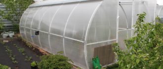
Greenhouse Harvest PC is an arch-shaped structure coated with polycarbonate. The structure is equipped with vents and a doorway, which allows for regular ventilation of the plantings. Each module is 2 m long.
Did you know? Icelandic farmers take advantage of the local benefits of nature and build naturally heated greenhouses near geysers.
Optionally, the structure can be extended by 2 m using additional modules. Also, at the request of the gardener, you can install side opening windows and partitions to distinguish between planted crops. This type should not be confused with the Harvest Plus greenhouse, which is smaller in size and covered with non-woven material.
pros
- The design has many advantages:
- the structure is easy to assemble;
- the frame is galvanized, which is why it is protected from corrosion;
- there are several options of different lengths with the ability to increase the area using two-meter inserts;
- polycarbonate sheets do not need to be drilled with self-tapping screws, since fastening tapes are needed for fastening;
- the end walls are equipped with openings for ventilation;
- the design is durable, withstands wind gusts of up to 20 m/s and snow loads of up to 20 kg/m²;
- if you do not install a foundation, the structure can be easily moved around the site;
- high thermal insulation rates allow seedlings to be planted as early as March – April;
- warranty for up to 20 years.
Minuses
- The Harvest PC greenhouse made of polycarbonate has two main disadvantages:
- for the winter, it is recommended to assemble the structure, attach supporting struts inside or cover it with a canopy;
- When used during rain, moisture from the upper edge of the window gets onto the plants.
However, these disadvantages are relative. If desired, the gardener can solve the listed problems.
"Harvest PCT"
Like the previously discussed models, the “Harvest PKT” is an arched greenhouse. The frame of the greenhouse is made of Larsen tongue and groove, which is a special Ω-shaped galvanized profile. Another feature of the model is that the gap between the trusses is 67 cm, which means that the number of arcs is greater and the strength of the structure is higher.
The four-meter greenhouse has 7 arcs. Thanks to these features, “Urozhay PKT” is considered one of the most load-resistant models in the “Urozhay” series.
"Harvest Classic"
The peculiarity of this model is a gable roof; the frame material is the same galvanized steel pipe as in other models. The standard set includes two doors and vents; it is possible to order additional vents for long greenhouses. The greenhouse consists of modules of 2 m, width - 2.5 m, height - 2.2 m.
Selection of drawings and optimal dimensions of the greenhouse
The minimum size of the greenhouse for Harvest PC is 4 m.
Basic design parameters:
- length - 4 m;
- width - 3 m;
- height - 2.15 m.
The kit for constructing a 4-meter greenhouse includes 3 sheets of cellular polycarbonate in the form of rolls 2.1 m long and 60–90 cm in diameter. The thickness of the material is 4 mm.
Did you know? The first greenhouses in Russia began to be built on the orders of Peter I.
If desired, the structure can be increased in length to 6 meters or more. To do this, just attach a two-meter extension. When choosing a drawing, pay attention to the distance between the arches. This figure should be 65 cm, which is the most suitable length for the specified thickness of the material. The width of the doors according to the manufacturer's drawings is 90 cm.
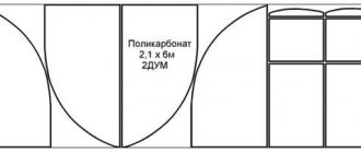
Before installation, the end walls for a basic four-meter structure must be cut according to the following drawing:
"Harvest Economy 2"
This model is a structure consisting of vertical walls and an arched roof. The frame for the material is made of steel V-shaped profile.
Polycarbonate sheets are secured using external ties. This model is available in a single size of 400x200x200 cm. The basic set contains 2 end doors and vents. The Harvest Economy 2 model is designed for heat-loving plants grown in spring and summer in a temperate climate zone.
In general, the “Harvest” series of greenhouses is easy to use; thanks to their sufficient height, they can be used with shelving. The durable frame eliminates the need to remove the greenhouse for the winter. Certain shortcomings that we mentioned above can be easily eliminated with a small amount of time and effort. What are your impressions of using these greenhouses?
Greenhouse for cellular polycarbonate “Harvest PK-6”
Greenhouse for cellular polycarbonate “Harvest PK-6”
General view of the greenhouse (Width 3 m. Length 6 m. Height 2.15 m.)
ASSEMBLY INSTRUCTIONS Greenhouse “Harvest Pk-6”
Thank you for purchasing our product. The products we produce are distinguished by the high quality of component materials, and the modern manufacturing method guarantees resistance to mechanical stress throughout the entire service life, provided that the assembly and installation instructions, as well as the care of the product, are followed. We wish you good harvests and hope that our products will fully satisfy your expectations.
Our products are protected by a hologram and the packaging contains the manufacturer's logos.
Attention!!! Beware of fakes.
1.
BASIC TECHNICAL DATA.
The greenhouse "Urozhay PK-6" is designed to create a microclimate favorable for growing garden crops in summer cottages and household plots.
The frame of the greenhouse is made of galvanized V-shaped profile with a thickness of 0.8 mm and is assembled using screws (m4x10, m4x14) and nuts.
Covering: cellular polycarbonate and U-profile. Attention!
Not included in the package, purchased separately
.
To cover the greenhouse you need four sheets of cellular polycarbonate measuring 2.1 x 6 m. and 31 pcs. endings (U-profile). Cellular polycarbonate is installed with a strictly defined side outward, which has a protective layer. The packaging film from the covering must be removed after cutting out the parts, before installing them on the frame. The covering at the ends of the greenhouse frame is secured with nuts (m4) and screws (m4x14, m4x25) with galvanized washers, and the top covering is fixed with clamping ties. Attention!
The mounting hardware is designed for a coating thickness of 4mm. The greenhouse "Harvest PK-6" is equipped with two ends with opening doors with vents and two reinforcements for the greenhouse frame. The PK-6 delivery set consists of four packages.
Also, if desired, you can additionally install reinforcements for the greenhouse frame, an upper arc-shaped opening window, extend the length of the greenhouse frame to 8 m, 10 m, etc., a multiple of two, extensions PC + 2 m and install a partition - amplifier. Attention! Sold separately
.
The greenhouse frame can be installed on a wooden frame, the recommended board is 50x150mm with dimensions 3x6m. (not included in the package, must be purchased and manufactured independently)
, as well as by digging into the ground; for this purpose, the delivery set includes supports for fixing in the ground.
Greenhouse dimensions:
Length 6m
Width 3m
Height 2.15m (when installed in the ground)
2.35m (when installed on a wooden frame)
The weight of the greenhouse frame is no more than 80 kg
Attention!
The manufacturer reserves the right to make changes to the design of the greenhouse without notifying the consumer.
2.
EQUIPMENT OF THE GREENHOUSE “Harvest PK-6”
| No., part no. | the name of detail | Part length (mm) | Quantity (PC) |
| 1 | Arc profile | 1610 | 30 |
| 2 | Arch extension | 860 | 20 |
| 3 | Arch extension support | 100 | 24 |
| 4 | Stringer | 1363 | 28 |
| 5v | Door post parts (upper) | 1145 | 4 |
| 5n | Door post parts (lower) | 1145 | 4 |
| 6 | Doorway lintel | 906 | 4 |
| 7 | Middle end cross member | 793 | 4 |
| 8 | Lower end cross member | 1004 | 4 |
| 9 | End jib | 1553 | 4 |
| 10v | Door pillar (upper) | 941 | 4 |
| 10n | Door pillar (lower) | 941 | 4 |
| 11 | Door cross member | 845 | 8 |
| 12 | Door jib | 993 | 4 |
| 13 | Window stand | 548 | 4 |
| 14 | Window cross member | 785 | 4 |
| 15 | Window jib | 894 | 2 |
| 16 | Stringer short | 696,5 | 7 |
| 17 | Bracket for fixing end cover | — | 10 |
| 18 | Arch reinforcement parts | 1468 | 6 |
| 19 | Arch reinforcement parts | 725 | 4 |
| 20 | Arch reinforcement parts | 400 | 4 |
| 21 | Hook for fixing doors and windows | 250 | 2 |
| 22 | Turntable for locking doors and windows | 100 | 4 |
| 23 | Tension tape | 5790 | 10 |
| 24 | Short tie tape | 350 | 10 |
| 25 | Door and window hinges | — | 8 |
| 26 | Screw M4 x 10 | — | 430 |
| 27 | Screw M4 x 14 | — | 180 |
| 28 | Screw M4 x 25 | — | 80 |
| 29 | Screw M4x35 | — | 10 |
| 30 | Nut M4 | — | 700 |
| 31 | Pressure washer | — | 120 |
| 32 | Corner | — | 18 |
Note: The cellular polycarbonate covering and the U-profile (the final strip for protecting the polycarbonate cellular structure from dirt and insects) are not included in the delivery package. Screw configurations are subject to change. Markings on parts of positions No. 1, No. 2, No. 3, No. 4 may not be on all parts, but on one part.
General instructions for assembly.
1. Frame parts are installed so that the side flanges of the profile face the covering.
2. The item number indicated in the package corresponds to the part number in the pictures and is indicated by the corresponding markings on the parts in the packaging. The marking of some parts has indexes: in
- top,
n
- bottom (along the height of the greenhouse)
k
- short (along the length)
3. The parts are connected by applying profiles and fastening with screws and nuts in two holes (Fig. 5-A, A1, B).
4. Corners No. 32 and brackets No. 17 are attached to the arches so that the inner corner of the corner faces the inside of the greenhouse.
5. Brackets No. 17 are designed for attaching the covering to the ends of the greenhouse.
6. In some parts there are free holes, which is not a defect, but a consequence of the unification of parts.
7. When assembling, be careful not to damage the parts, since they do not have sufficient rigidity until final assembly.
8. To assemble the greenhouse you will need: M7 wrench, cordless screwdriver or electric. drill, M4 drill, Phillips or flat-head screwdriver, depending on the screw configuration, sharp knife with replaceable blades, transparent tape, pliers, el. jigsaw or fine-tooth saw, 7m tape measure, marker, el. extension cord, ruler 1 m or more, stepladder.
3.
SEQUENCE OF ASSEMBLY OF THE GREENHOUSE “Harvest PK-6”.
3.1. Assembly of the arc amplifier.
3.1.1. Take one arcuate profile No. 1 (complete set) and extend it on both sides with arcuate profiles No. 1, securing with m4x14 screws, installing them on the side of the concave part of the profile
(see Fig.4-A, A1).
3.1.2. Attach arch extension No. 2 and M4x14 screws to the ends of the resulting arc (see Fig. 3).
3.1.3. Attach 3 pieces to the resulting arch. arch reinforcement No. 18, putting m4x14 screws on the protruding parts and tightening with other nuts (see Fig. 3.1-A, B).
3.1.4. At the top of the arch, connect amplifiers No. 18 with two amplifiers No. 20 (m4x14 screw). Install the fastening screws on the side of the convex part of the profile (see Fig. 3.1-B).
3.1.5. In the lower part, connect amplifier No. 18 to arch extension No. 2 with amplifier part No. 19 (m4x14 screw) (see Fig. 3.1-D, E).
3.1.6. Similar to paragraph 3.1. assemble the second arch booster.
3.2. ASSEMBLY OF ARCHES.
3.2.1. The assembly of the arches is similar to paragraphs 3.1.1. and 3.1.2. using M4x10 screws (see Fig. 4-A, A1).
3.3. DOOR OPENING ASSEMBLY.
3.3.1. Take the doorway post parts No. 5v and No. 5n (see Fig. 2) and connect them together with m4x10 screws (see Fig. 5- A1, A).
3.3.2. Attach angle No. 32 (m4x10 screw) to the upper part of part 5c (see Fig. 5-B).
3.3.3. Take two door frame posts
clause 3.3.2. and connect them together with two jumpers No. 6 (m4x10 screw) (see Fig. 5-B).
3.4. END ASSEMBLY.
3.4.1.
Take one finished arch from point 3.2.1. in the center at the top, attach bracket No. 17 (m4x10 screw) (see Fig. 5-G).
3.4.2. Attach corners No. 32 to the doorway in paragraph 3.3.3. to the arched part of paragraph 3.4.1. placing the doorway in the center of bracket No. 17 (see Fig. 5-B).
3.4.3. Attach angle No. 32 to the cross member of the bottom end No. 8 with one m4x10 screw.
3.4.4. Attach the free end of the lower end cross member No. 8 to the doorway in paragraph 3.4.2. opposite the bottom jumper No. 6 with two m4x10 screws (see Fig. 5-D).
3.4.5. Corner No. 32 of paragraph 3.4.3. attach to the arched part with two m4x10 screws (see Fig. 5-E).
3.4.6. Similar to paragraphs 3.4.3-3.4.5. connect the doorway to the arched part on the other side.
3.4.7. Attach angle No. 32 (m4x10 screw) to the end jib No. 9.
3.4.8. From the side where angle No. 32 is attached to the jib of end No. 9, attach the middle cross member of end No. 7 with the side at an angle (see Fig. 5-D).
3.4.9. Attach the free end of the jib No. 9 to the connection unit of the doorway to the lower cross member of the end No. 8 (see Fig. 5-D).
3.4.10. Attach the free end of the middle crossbar No. 7 to the doorway (see Fig. 5-B).
3.4.11. Attach corner No. 32 of paragraph 3.4.7. to the arched part (see Fig. 5-D).
3.4.12. Similar to paragraphs 3.4.7.-3.4.11. attach jib No. 9 and middle cross member No. 7 on the other side of the doorway.
3.4.13. Install brackets No. 17 in the amount of 4 pieces into the free hole of the arch. (See Fig. 5-G).
3.4.14. Similar to paragraphs 3.3.1. – 3.4.13. assemble the second end.
3.5. DOOR ASSEMBLY.
3.5.1. Take two door posts No. 10v and No. 10n and connect them with two m4x10 screws (see Fig. 6-A, A1).
3.5.2. Connect the two door posts assemblies in step 3.5.1. between themselves by four door crossbars No. 11 (screw m4x10) (see Fig. 6-B, E).
3.5.3. At the junction points of the door posts with the crossbar No. 11, attach the door jibs No. 12 (see Fig. 6-C, D, E).
3.6. ASSEMBLY OF THE WINDOW.
3.6.1. Take two vent posts No. 13 and connect them to each other with two crossbars of vent No. 14 (screw m4x10) (see Fig. 6-E).
3.6.2. In the junction of parts No. 13 and No. 14, install the vent jib No. 15 (m4x10 screw) (see Fig. 6-B).
3.7. Covering the side parts of the end with polycarbonate.
3.7.1. Take a sheet of polycarbonate measuring 6x2.1 m and draw a line along the sheet with a marker along the middle for a length of approximately 3.60 m (see Fig. 7).
3.7.2. Place the end frame on this sheet so that the center along the profile of the doorway post lies on the line, and the lower cross member No. 8 is flush with the end of the sheet and, using a marker, outline the radius of the end on one side with a marker.
3.7.3. Cut out the outlined part of the covering with an overlap of approximately 3-4 mm.
3.7.4. Attach the cut out part of the covering to the end frame on one side and on the other
(see Fig. 8), check that the cover is cut correctly and make changes if necessary. Take the cut-out cover piece and, using it as a template (subject to modifications), draw the remaining three end cover blanks on a sheet of polycarbonate (see Fig. 7).
3.7.5. Cut out the covering details with a jigsaw.
3.7.6. Remove the protective film from the cover. Mark the side facing out with a marker. Place the end (U-profile) onto the edges of the covering piece to prevent contamination and to stiffen the sheet where the hinges are attached. From the radius part of the coating, the U-profile must be cut with a wedge from one wide side approximately
after 10-12 cm. In order to prevent arbitrary removal of the end, temporarily fix
the U-profile at the edges with transparent tape.
Bend the edges of the tape to make it easier to remove. 3.7.7. Secure the side part of the covering to the end frame with screws (M4x14, M4x25) and washers
by drilling holes in the polycarbonate at the fastening points (see Fig. 8). Similar to paragraphs 3.7.6., 3.7.7. secure the covering on the other side of the end.
3.8. COVERING THE DOOR AND WINDOW WITH POLYCARBONATE.
3.8.1. Take the end of the greenhouse (clause 3.7.7.) and place it on a flat area. In the doorway
lay the door frame (clause 3.5.) and the windows (clause 3.6.), measure the dimensions of the door covering, taking into account allowances and overlaps.
3.8.2. Measure the dimensions of the door covering on the remaining part of the sheet (clause 3.7.5.) and cut with a sharp knife (see Fig. 7).
3.8.3. Place the door covering on the frame of the door and window (section 3.8.1.) and check that the size of the door covering you cut is correct. On a sheet of door covering, mark the dimensions of the window with a marker and cut out the window covering with a sharp knife (see Fig. 9).
3.8.4. Remove the protective film from the door and window coverings in paragraph 3.8.3. (don't forget to mark the side facing the sun with a marker).
3.8.5. Install the end along the contour of the door and window covering to stiffen the covering at the hinge fastening points and prevent contamination of the polycarbonate.
3.8.6. Fasten the covering to the door and window frames using M4x14 and M4x25 fastening screws with washers (see Fig. 10).
3.9. ATTACHING THE DOOR AND WINDOW TO THE END OF THE GREENHOUSE.
3.9.1. Drill holes in the covering where the hinges are attached. Fasten hinges No. 25 on top of the cover on the window and on the door (m4x14 screw).
Attention! Install the screws for fastening the hinges to the window, to the door from the side of the frame profile.
3.9.2. Connect the window to the door, and the door to the doorway (clause 3.7.7.) at the hinge fastening points with M4x14 screws. Attention! Install the screws for fastening the hinge of the window to the door on the side of the door frame profile, and install the screws for fastening the hinge of the door to the doorway from the side of the hinges and the cover.
3.10. INSTALLATION OF TURNABLES.
3.10.1. Install two turntables on the doorway post on top of the covering, placing washers under the turntables. One for fixing the door, the other for the window. Use M4x25 screws with two locknuts
3.11. COATING THE UPPER PART OF THE END WITH POLYCARBONATE.
3.11.1. Measure the distance between the side coverings of the end (clause 3.7.7.) and the distance from the top of the window covering (clause 3.9.2.) to the top of the end arch (see Fig. 8, 10).
3.11.2. Cut a rectangle from the remaining polycarbonate sheet (clause 3.8.2.) with the dimensions of clause 3.11.1. (see Fig. 7). Attention! The location of the honeycomb coating should be vertical along the height of the end.
3.11.3. Remove the protective film, mark the side facing the sun with a marker, and install the ending on one of the sides (along the width of the doorway).
3.11.4. Attach the rectangle (clause 3.11.3.) to the end with the end to the window and secure with M4x14 screws and washers in the places where the covering is attached (see Fig. 8).
3.11.5. Cut off the protruding parts of the rectangle. jigsaw along the radius of the end and install the end according to paragraph 3.7.6.
3.11.6. Similar to paragraphs 3.7.-3.11. cover the second end.
3.12. ASSEMBLY OF THE FRAME.
3.12.1. Take the assembled end (section 3.11.6.) and place it on a flat area with the coating down. In the places where brackets No. 17 are attached, unscrew the nuts from the screws and install stringers No. 4, screwing the nuts back (see Fig. 11).
3.12.2. Attach stringers No. 4 to arch extensions No. 2 (m4x10) (see Fig. 13).
3.12.3. In the center of the stringers No. 4 attached to the end, attach the arch (clause 3.2.) (m4x10).
3.12.4. In order to prevent bending of the metal structure and for ease of assembly, temporarily fix the next arch to the stringers with one screw at three points, in the arch extensions and along the top of the greenhouse. Install two screws (m4x10) into the free holes for fastening stringers in the arched part, install the free end of the stringer
(clause 3.12.1.) and extend it with the next stringer No. 4 and tighten these three parts with nuts (see Fig. 12). After attaching the stringers in the free holes, unscrew the nuts from the fixing screws, extend the stringer with the next stringer No. 4 and connect the three parts together (see Fig. 12).
3.12.5. Lift the end and install it on arch extensions #2. Perform further assembly using a stepladder. Install the arch with the amplifier of point 3.1. and attach to the stringers of paragraph 3.12.4. Attention !!! An arch reinforcement is installed every 2m. length of the greenhouse.
3.12.6. Further assembly of the tunnel is carried out by placing arches on top of the stringers and fastening in accordance with paragraphs 3.12. with connection at the end end vertically.
4. INSTALLING THE GREENHOUSE FRAME
ON A WOODEN FRAME.
4.1. Before installing the greenhouse frame on a wooden frame, it is necessary to install the fastening screws (point 6.1. instructions) for the tie strips (see Fig. 13). Recommended board for a greenhouse frame 50x150 mm. You will need two 3m and two 6m boards.
4.2. Measure along the end the internal distance between the extensions of arches No. 2. Measure at 3 m. boards this distance, and cut off the excess. Make two cuts along the width of the board to a depth of 15mm, and 40mm wide in the places where the doorway is attached. Secure the boards using self-tapping screws.
4.3. Measure the distance between the end boards along the length of the greenhouse and measure at 6m. boards, cut off the excess. Install these boards between the ends and secure them along the edges of the boards and in the arch extensions with self-tapping screws.
4.4. Treat the boards with an antiseptic against rotting.
Attention! Frame, screws and antiseptic are not included in the delivery set. Purchased separately and made independently.
5. INSTALLING THE FRAME IN THE GROUND.
5.1. To fasten the frame in the ground, the delivery set includes supports No. 3 (see Fig. 13).
Attach supports to the ends of the arch extensions and doorway posts. Each support is fastened with two screws (m4x10) located diagonally.
Attention! Before burying the frame in the ground, it is necessary to cover the greenhouse tunnel
polycarbonate and install tie strips.
6. COATING THE UPPER PART OF THE GREENHOUSE TUNNEL.
6.1. Install screws (m4x14) from the inside of the greenhouse to fasten the tie strips on the arch extensions No. 2 and tighten with nuts. The fastening screws must be located below the level of the lower cross member of end No. 8 (see Fig. 13, 14 position 27).
6.2. Take a 6m sheet of polycarbonate and remove the packaging film from both sides. Place an ending (U - profile) on the ends of the covering sheet.
6.3. Place the covering on top of the arched part of the greenhouse so that the edge of the sheet protrudes beyond the end by about 5cm.
6.4. Take the parts of the tie tape No. 23 and No. 24 and connect them together with an M4x35 screw, do not tighten the nut completely. Place the pressure tape on top of the sheet along the middle arches, put it on the protruding parts of the screw in paragraph 6.1. and secure with nuts.
6.5. Check that the greenhouse frame is installed correctly and the covering is positioned vertically and horizontally, then tighten the M4x35 tightening screw. (see Fig. 14 item 29). Attention!!! Attach the outer sheets of the top covering (at the ends) to three ties, leave space for attaching the upper central cover, which is attached with an overlap over the outer sheets.
6.6. Install the second sheet of covering on the other end of the greenhouse and secure it with ties according to paragraphs 6.2-6.5.
6.7. Similar to paragraphs 6.2.-6.5. install the third sheet in the middle of the greenhouse, overlapping the previous sheets.
7. INSTALLING A HOOK FOR FIXING THE DOOR AND WINDOW.
7.1. On the middle cross member of end No. 7, on top of the covering, install corner No. 32, placing a washer under the corner at the fastening points. Place hook No. 21 in the corner (see Fig. 15).
7.2. On the crossbar of window No. 14 and door No. 11, install one corner No. 32 on top of the covering, also placing a washer under the corner at the fastening points (see Fig. 16).
7.3. Similarly, install corners No. 32 and hook No. 21 to secure the door and window at the other end.
8. REQUIREMENTS FOR OPERATING CONDITIONS
.
8.1. The covered greenhouse is designed for a snow load of no more than 20 kg/m2 and wind
speed no more than 20m/sec.
8.2. Due to the oscillatory movements of the greenhouse due to gusts of wind, it is necessary to tighten the loose fastening nuts or replace the fasteners.
8.3. In winter, due to snow load, in order to avoid deformation of the frame, we recommend removing the top sheets of the greenhouse cover or strengthening the top stringer T
- figurative
wooden supports (50x100 board), placing them inside the greenhouse every meter of the length of the greenhouse. Attention! Wooden supports are not included in the delivery set; they are made independently.
